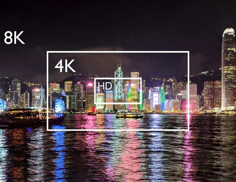
Product development in the cable and adapter industry often combines proven reference designs with practical innovation. During this process, engineers may encounter both successful solutions and design failures. Sharing these experiences can help other technical teams reduce development time, avoid common mistakes, and improve product reliability.
This article introduces the design of a USB Type-C to DisplayPort product based on Chrontel’s CH7213A. It explains the relevant USB Type-C port roles, DisplayPort Alternate Mode configuration, resolution support, common display problems, and key PCB layout considerations.
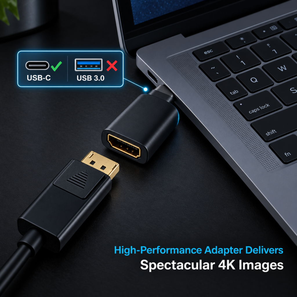
Understanding DisplayPort Alternate Mode over USB Type-C
VESA and USB-IF defined DisplayPort Alternate Mode to enable DisplayPort audio and video signals to be transmitted through a USB Type-C connector and cable.
Before discussing the product design, it is important to understand the USB Type-C and DisplayPort port roles.
DFP-U: Downstream-Facing Port for USB
A DFP-U normally refers to the USB Type-C port on a host device, such as a computer, tablet, or smartphone. It provides the downstream USB connection to a peripheral.
UFP-U: Upstream-Facing Port for USB
A UFP-U normally refers to the USB port on a peripheral that connects to a host. Common examples include USB flash drives, dongles, and other USB devices.
DFP-D: Downstream-Facing Port for DisplayPort
A DFP-D supports DisplayPort Alternate Mode and normally operates as the DisplayPort source. Typical source devices include computers, tablets, and smartphones with USB Type-C video output.
UFP-D: Upstream-Facing Port for DisplayPort
A UFP-D receives the DisplayPort signal through USB Type-C. It is generally found in DisplayPort display devices or USB Type-C video adapters.
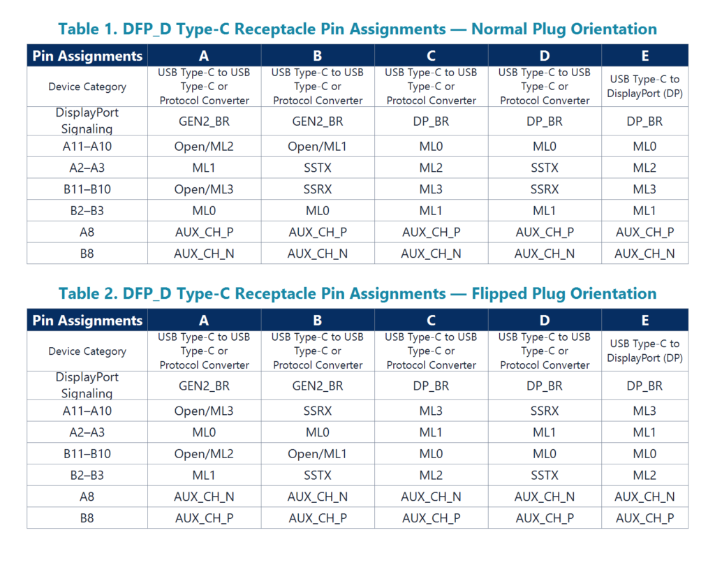
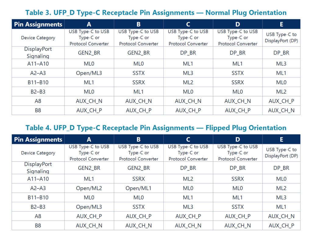
Selecting the Pin Assignment
DFP-D and UFP-D configurations use different DisplayPort Alt Mode pin assignments. These assignments define how the DisplayPort Main Link, AUX channel, USB data, and other signals are mapped to the USB Type-C connector.
[Insert the USB Type-C DisplayPort Alt Mode Pin Assignment diagram here.]
The USB Type-C to DisplayPort product discussed in this article must connect to a source device that supports DisplayPort Alternate Mode. On the USB Type-C side, the adapter therefore operates according to the required UFP-D configuration.
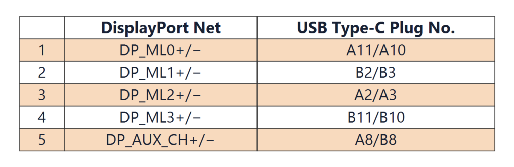
This design uses Pin Assignment E as specified in the original design requirements. The corresponding pin mapping should be checked carefully against the selected CH7213A reference design and the applicable version of the VESA DisplayPort Alt Mode specification before the PCB is finalized.
Using the CH7213A for CC Logic Control
The design uses Chrontel’s CH7213A for USB Type-C Configuration Channel logic control. Its compact QFN package helps reduce the required PCB area, making it suitable for small adapters and cable-integrated products.
According to the original design requirements, the CH7213A provides the following functions:
- USB Type-C CC logic control
- DisplayPort Alternate Mode negotiation
- AUX channel monitoring
- Billboard function support
- Low-power operation
- No external Ra resistor requirement
- Firmware upgrade support
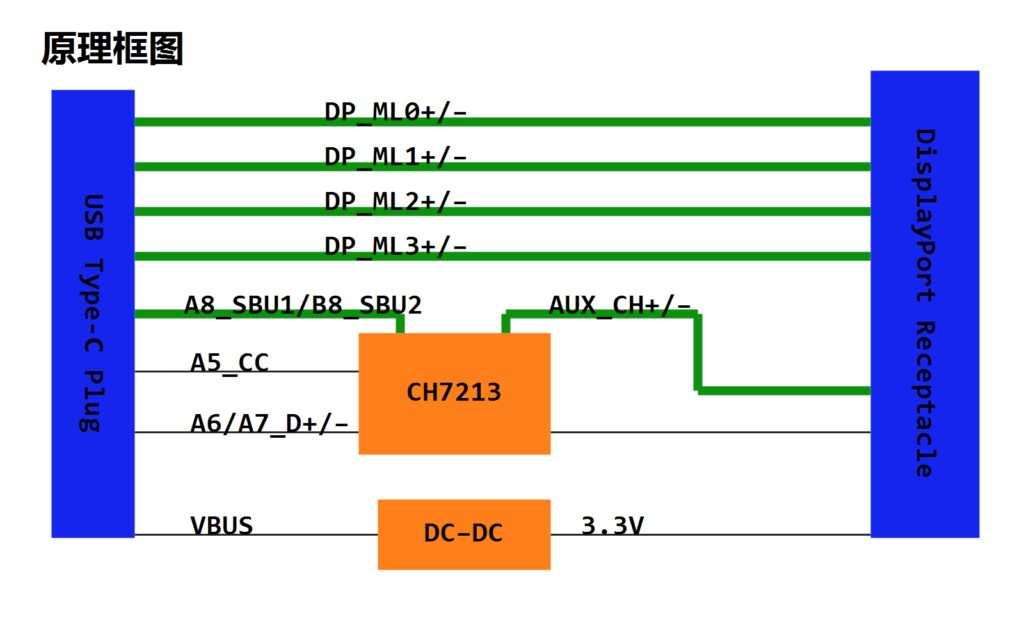
The CH7213A is not used to convert the video signal. The DisplayPort Main Link signal passes between the USB Type-C source and the DisplayPort output. The device primarily manages CC communication and the control functions required to enter DisplayPort Alternate Mode.
The physical product described here uses a USB Type-C male connector at the source end. At the output end, the DisplayPort cable is soldered directly to the PCB and terminated with a DisplayPort male connector for connection to a monitor.
Frequently Asked Questions
1. Does this USB Type-C to DisplayPort design support 4K at 60Hz?
The maximum output resolution depends on both the source device and the connected display.
Because the CH7213A does not convert or process the video signal, the adapter cannot increase the resolution supported by either device. To display 4K at 60Hz, the USB Type-C source must support the required DisplayPort Alt Mode output, and the monitor must support the same resolution and refresh rate.
The cable assembly and PCB must also provide sufficient signal integrity. If the source, display, cable, and adapter PCB all meet the required specifications, the system can output 4K at 60Hz.
2. What causes an unstable, flickering, or intermittent DisplayPort image?
Display instability may be caused by several factors.
Insufficient signal strength from the source
Some source devices provide a weaker DisplayPort signal through their USB Type-C ports. In this situation, a cable or adapter with high insertion loss may cause flickering, intermittent video, or complete loss of display.
Poor cable signal integrity
A low-quality DisplayPort cable can introduce excessive attenuation, impedance discontinuities, crosstalk, and reflections. These problems become more noticeable at higher resolutions and refresh rates.
Improper PCB layout
Poor PCB routing can interrupt the high-speed signal return path, create impedance discontinuities, or introduce excessive skew between differential signals. Even if the circuit design is correct, an unsuitable PCB layout can still cause an unstable display.
Troubleshooting should therefore consider the entire signal chain rather than focusing only on the CC controller.
PCB Stack-Up and Layout Considerations
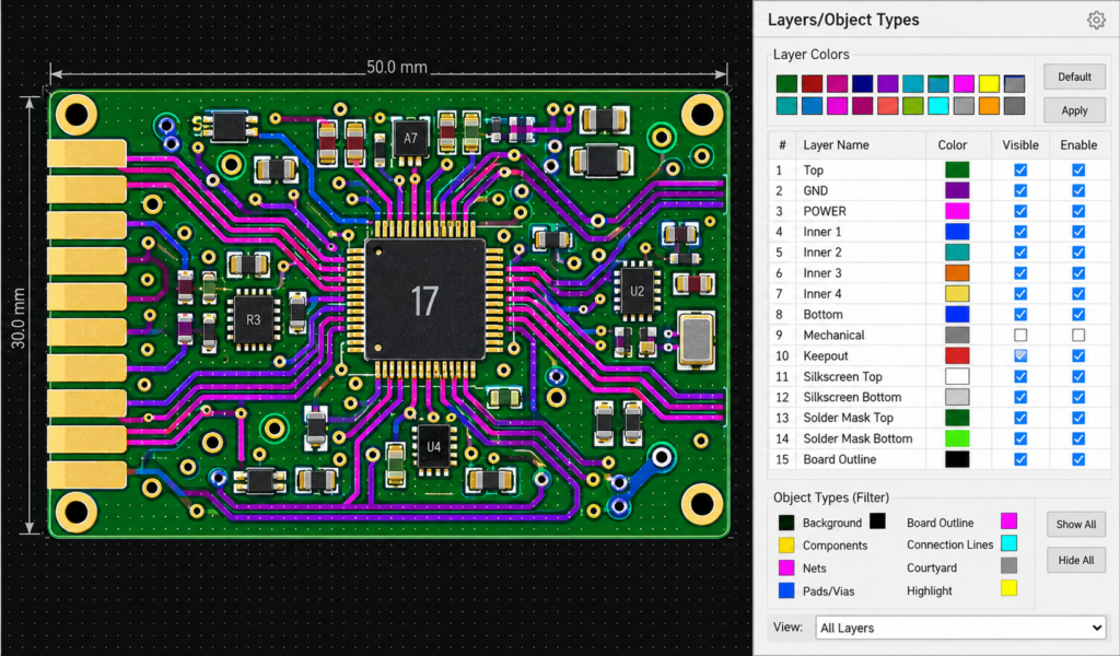
The product was originally intended to use the following six-layer stack-up:
- S1
- GND
- PWR
- S2
- S3
- S4
However, the actual PCB used a different arrangement:
- S1
- S2
- S3
- PWR
- GND
- S4
For improved high-speed signal integrity, the recommended stack-up is:
- S1
- GND1
- S2
- S3
- GND2
- S4
This arrangement provides nearby reference planes for the high-speed signal layers and helps maintain more continuous return-current paths.
1. Do not split the reference plane with vias
In the original layout, the four DisplayPort differential pairs passed through vias positioned almost side by side. This created a barrier in the reference copper and interrupted the return-current path.
High-speed differential signals require a continuous reference plane. The via positions should therefore be adjusted so that they do not divide the reference plane. Ground stitching vias should also be positioned appropriately near signal-layer transitions to support the return-current path.
[Insert the original and revised via-layout comparison here.]
2. Control differential-pair length matching
The four DisplayPort Main Link differential pairs, ML0 through ML3, require controlled length matching.
According to the original design target:
- Length mismatch within each differential pair should be controlled within 5 mil.
- Length mismatch among the four Main Link differential pairs should be controlled within 10 mil.
The original PCB layout showed a relatively large difference in length between the differential pairs. The routing should be adjusted to reduce skew and maintain more consistent signal timing.
The final requirements should follow the PCB manufacturer’s process capability, the Chrontel reference design, and the applicable DisplayPort specification.
3. A dedicated 3.3V power layer may not be necessary
The 3.3V rail carries relatively low current and does not directly supply a high-power, high-speed video-processing device. It may therefore be unnecessary to reserve an entire PCB layer exclusively for 3.3V.
The available layer can instead be used to provide a more complete ground reference for the high-speed signals.
4. Route high-speed differential signals on the outer layers when practical
Routing the DisplayPort differential pairs on an outer layer can reduce the number of vias and signal-layer transitions. Fewer transitions generally mean fewer impedance discontinuities and a more predictable return path.
However, the final routing strategy should still be based on the selected PCB stack-up, impedance calculation, electromagnetic compatibility requirements, and mechanical constraints.
5. Verify every signal layer against its reference plane
After routing is complete, display each signal layer together with its corresponding reference plane. Check whether the reference plane remains continuous beneath the entire high-speed route.
Special attention should be given to:
- Differential-pair vias
- Plane splits and voids
- Connector transitions
- Ground stitching vias
- Trace-width and spacing changes
- Pair-to-pair spacing
- Unnecessary stubs
- Return-current discontinuities
Conclusion
A reliable USB Type-C to DisplayPort product depends on more than correct CC logic. The CH7213A can manage USB Type-C communication and DisplayPort Alternate Mode entry, but video performance still depends on the complete high-speed signal path.
The source device, display, cable, connector, PCB stack-up, differential-pair routing, impedance control, and reference-plane continuity must all be considered together.
For stable 4K@60Hz output, designers should validate both functional compatibility and signal integrity. Careful PCB layout, proper cable selection, and complete system testing are essential for preventing flickering, intermittent video, and display failures.